FabNC
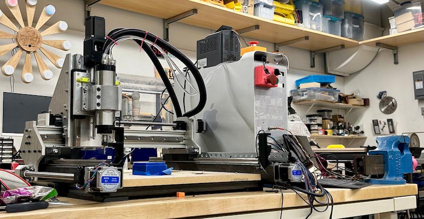
A scratch-built CNC mill engineered for real metal-cutting power and precision.
Project Overview
Why?
As graduation approached, I felt a growing urgency: I was losing access to MIT’s makerspaces — the place where I learned how to make (almost) anything. Going back home to Palestine meant entering an environment where this kind of infrastructure simply doesn’t exist. It was a bit suffocating. Imagine: Just as you start to believe that you can make anything, the infrastructure that would've enabled you to do so suddenly vanishes.
I didn't want that limitation to dictate what I could build. At the same time, I was finishing my incomplete in How to Make (Almost) Anything, fully immersed in Neil Gershenfeld’s vision of Fab 2.0 and Fab 3.0—a future where digital fabrication becomes globally accessible, and where machines don’t just make products, but eventually make other machines. The idea that manufacturing could be decentralized, shared, and self- propagating felt like its own kind of utopia.
From these dreams, a concrete challenge was born: my graduation gift to myself would be to build my own CNC mill from scratch-An opportunity to actually see the current reality of this vision, and to make a machine that could bootstrap future projects, future tools, and eventually a small-scale fabrication lab that others could benefit from too. Moreover, it was a test of my performance in the face of a complex project that is largely outside of my domain of expertise.
Constraints and scope:
I wanted a CNC mill that would be good enough for most of my needs. It might not be specialized for any specific application, but it should be able to handle most of the tasks i would need a CNC mill for adequately. In particular, I wanted a machine that would be capable of machining the parts I would need to build a larger CNC mill(that whole fab 2.0 idea of a self sustainable fab lab). The specific context where I am buildling this CNC in MIT and then taking it with on a flight to Palestine imposed its own constraints and hueristics. For one, for the sake of cost effectiveness, the plan is to take the machine in a checked bag. This means that for the size of the machine to be maximal, it should be made of assembled parts that can be disassembled and reassembled. Moreover, the size of the parts is constrained by the size of the checked bag. This constraint practically define the size of the machine since I am looking to maximize the machine's cutting volume. Another hueristic that is introduced is that the machine should relatively light-weight(flight). This is challenging since milling machines often rely on mass to be able to handle resonant frequencie. The structures used to enforce the machine's rigidity are also heavy. The primary objective function to optimize is the cost of the machine. Not necessarily the absolute material cost, but rather the cost that I could personally get the parts for. In other words, salvaged parts and parts that use salvaged scraps as stock are favored as long as it is feasible to meet the constraints if these parts are used. other than the ones previously mentioned, the constraints were that the machine should be precise and stiff enough to to be capable of successfully machining later iterations of the parts used in the machine.
Research/approach?
Design
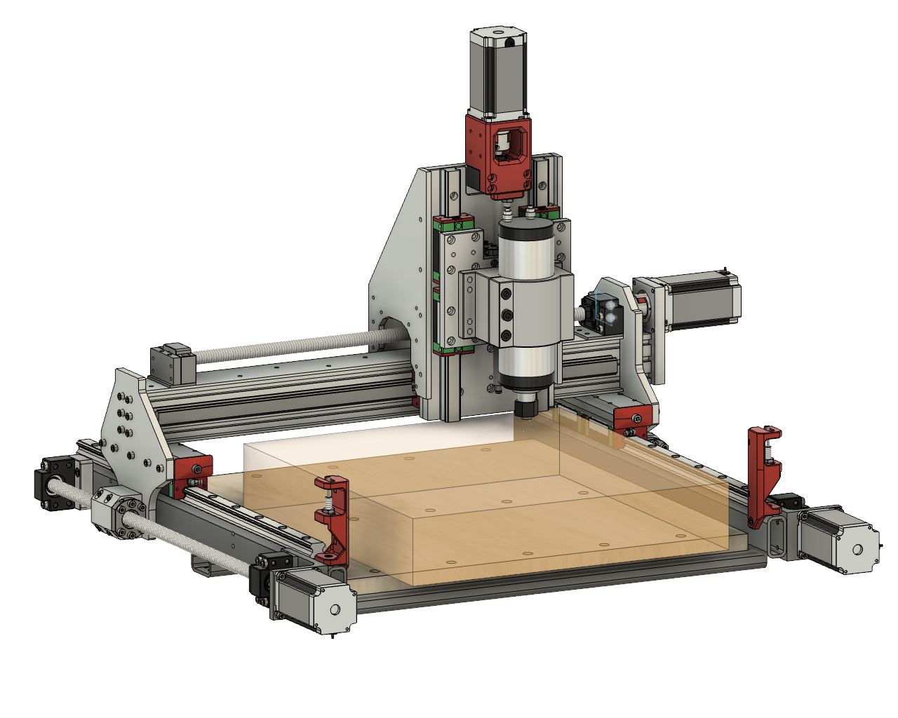
The translucent box depicts the cutting volume. It boasts a volume of 415x435x80mm. Note that the cutting volume extends beyond the spoilboard. This is intentional, and the goal is to leverage this portion to fixture and machine parts with a height that exceeds the spoilboard. This significantly expands the types of operations that the machine is capable of. Most importantly, it allows us to drill and tap hold into the side of plates(something needed for several parts of the machine). I started from PrintNC's design. The main reasons are: It had the most resources available for building it. The design is open source, a guide for building it was available along with an active community supporting the project. it was on its fourth iteration. So, it was a well tested desigm with it was also parametric to an extent. thhis meant that i could easily modify the dimension of the frame of the machine to meet the constraint. the design quickly reached a point where only around a handfull of parts were shared with PrintNC. Many factors led to this. For starters, when sourcing the precision linear motion components, i was able to get a much better deal on components that were slightly longer than the ones used in the PrintNC design with my specified dimensions(i couldn't be super picky about the length since i was sourcing them from amazon). This meant that if the design is to be built as is, the steel tubing used to build the frame would be too long to fit in a checked bag. Moreover, the cheapest source steel tubing(an MIT makerspace that sells a small selection of materials) only had 1" by 2" tubing or smaller. the 2" was good. however, the 1" was too small to accomodate the stepper motor mount and the part that couples theball screw nuts to the gantry. I also had an inner desire to make the design my own. the other major shift is that i decided to use T-slot aluminum extrusions instead of steel tubing for the gantry beam. aluminum instead of steel because it is lighter. In addition, T-slot extrusion had the practical upside that you could tap its end which provided a straightforward mounting surface for the x-axis stepper motor mount. and a method to couple the y-axis linear motion components to the gantry beam. i ended up going with two 2060 aluminum extrusions for the gantry beam that Anthony Pennes(MIT technical instructor at EDS, the GOAT) generously donated to me. Anthony was also kind enough to advise me through the whole process of building this machine. i also did not like the idea of mounting a linear rail on the bottom of the gantry beam. i especially did not like it since a lot of the z axis' range of motion was already eaten up due do the smaller steel tubing. i ended up going with a linear rail mounted on the front and back of the gantry beam. i also added coupling plates at the top and bottom of the gantry beam to couple/box the two 2060 aluminum extrusions to increase the rigidity the gantry beam. the rest of the design changes follow as a result of the these major changes or in the same vein of material availability. for insteance, I luckily stumbled upon a large and thick steel angle that was perfect for the Y-axis stepper motor mount. the resulting motor mount was much more stiff than the one used in PrintNC and frankly much more stiff than required. But, it was free and the stiffness was welcome. machining the steel angle to establish the mounting and locating surfaces and ensure the angle was a precise 90 degrees was a time consuming but insightful challenge.
Electronics
System block diagram overview: AC mains enter a latching safety circuit and then split to the 24V and 48V power supplies plus a line filter feeding the VFD. The 24V supply powers the FlexiHAL motion controller, while the host PC connects over USB-C. FlexiHAL outputs step/dir control signals to the axis drivers (X/Y/Z/Y2), RS485 to the VFD for spindle control, and limit switch/IO lines to the machine. The 48V supply powers the axis drivers, which drive the stepper motors, while the VFD drives the spindle.
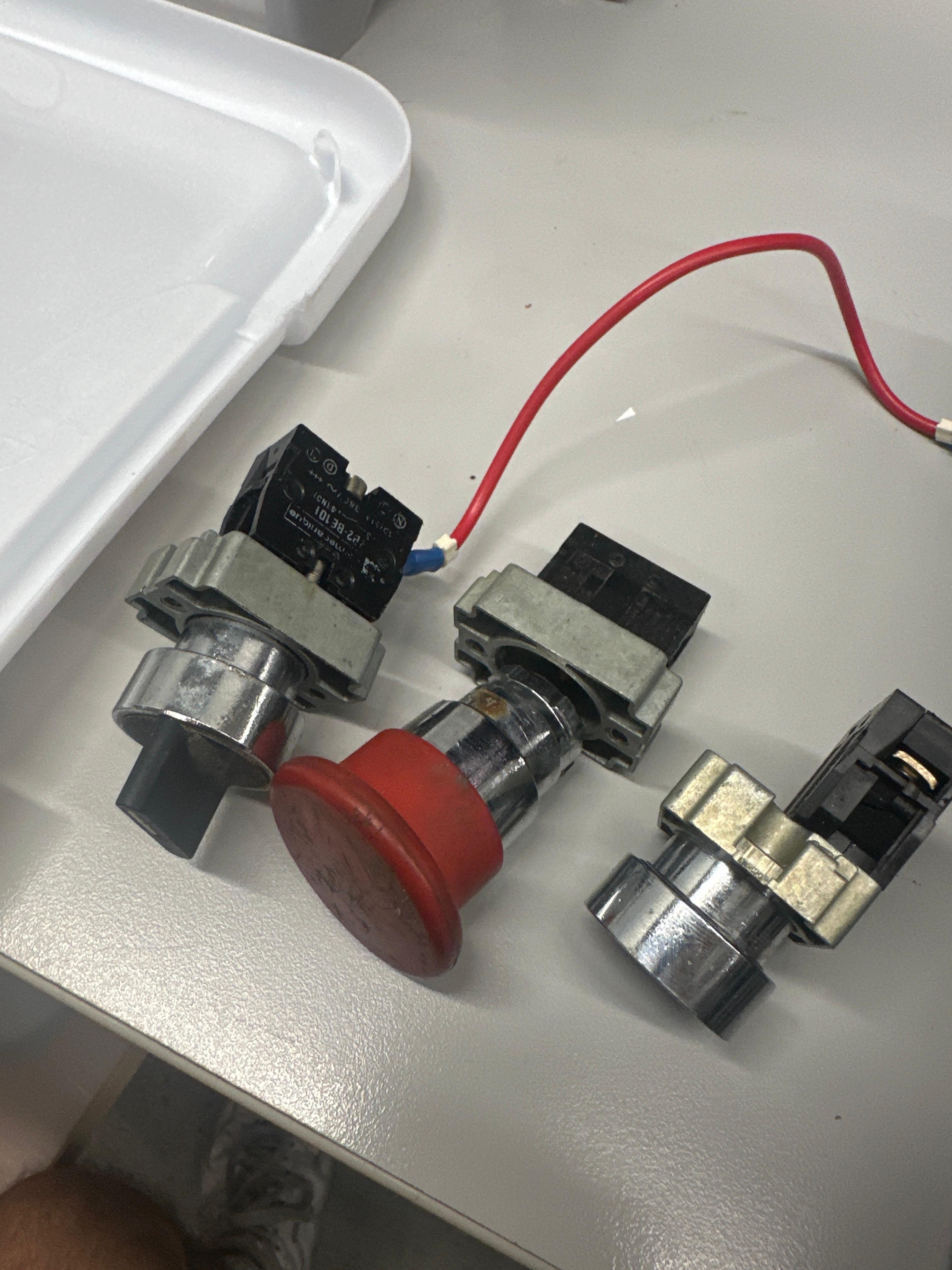
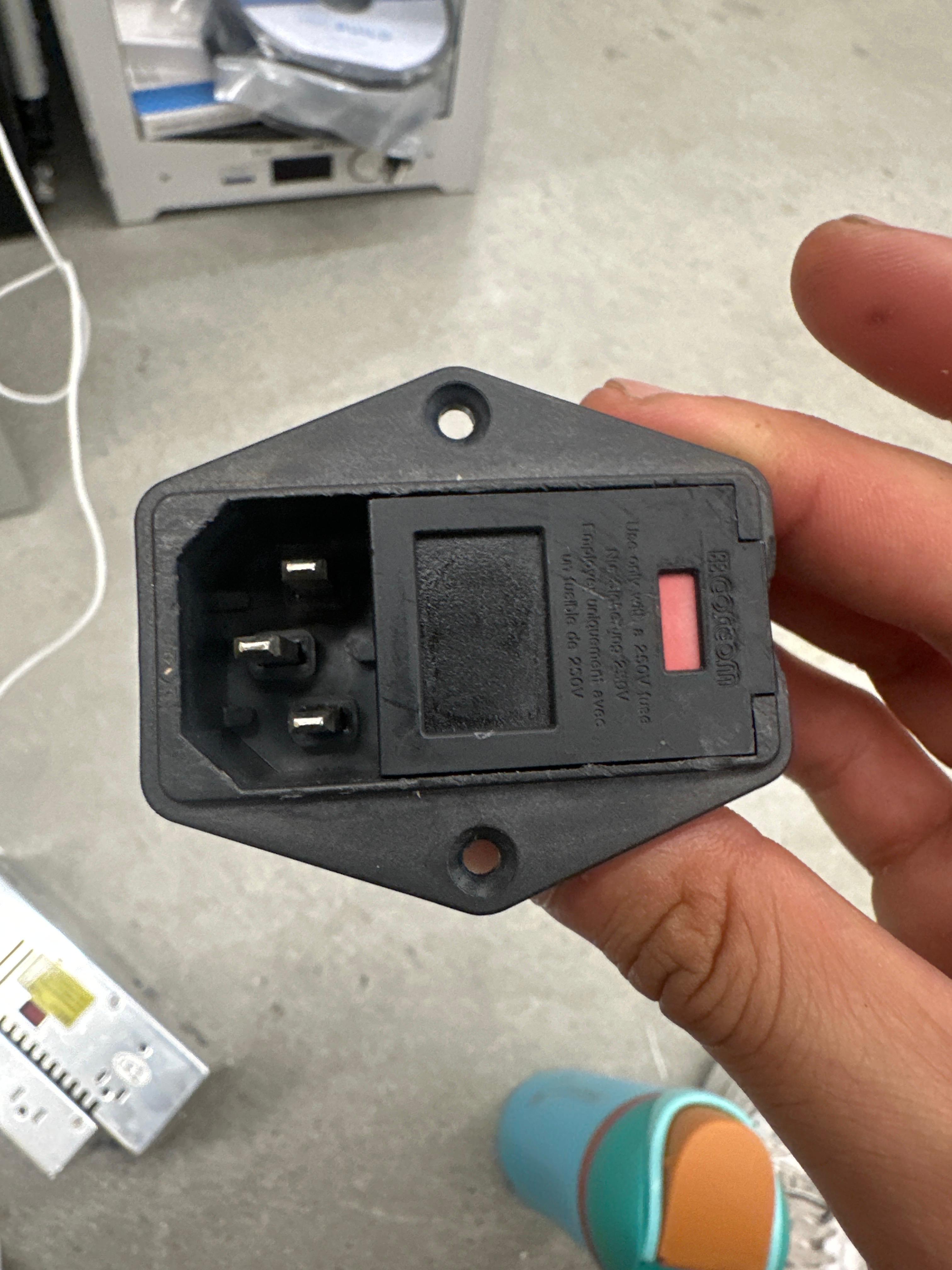
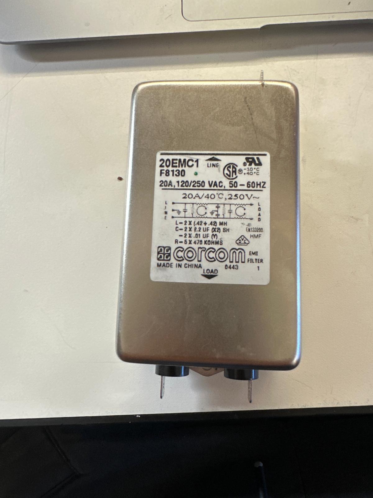
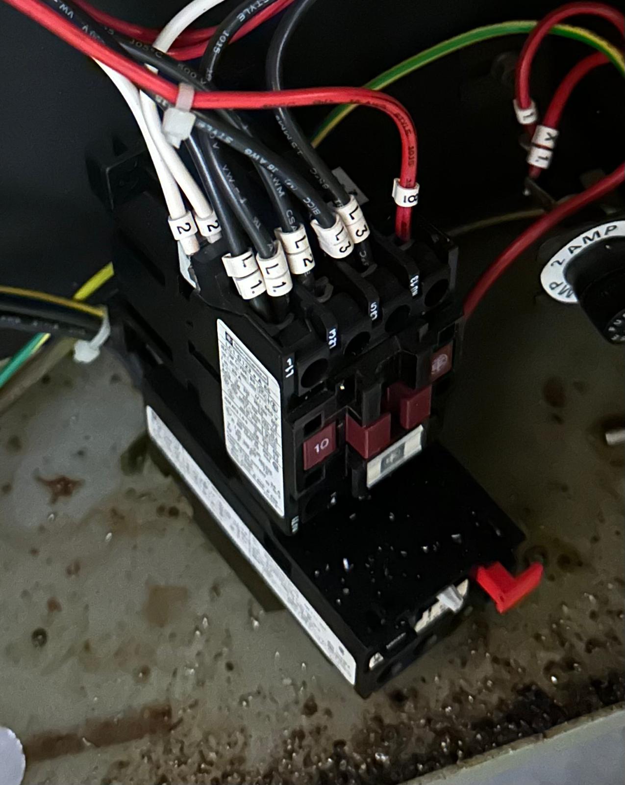
Electronics Salvaged from Old Machinery and Repurposed for FabNC: Switches, Power Inlet, Line Filter, and Contactor. The Contactor (bottom right) is broken and was not used.
Since PrintNC's electronics architecture was already pretty mature, I mostly inherited its structure and adapted it to my constraints. I sourced components with dual-voltage ratings since I was building and testing in a 110V environment but the machine will live in a 220V one. That meant verifying AC-rated components (PSUs, contactor, breaker, line filter, VFD) for 100–240V compatibility. Most parts were straightforward, but I missed the fine print on a VFD that claimed 100–240V and was actually 220V-only. I ended up using a spare VFD from MIT's Deep makerspace with matching output specs (generously donated by Seth), which solved the issue without compromising the system.
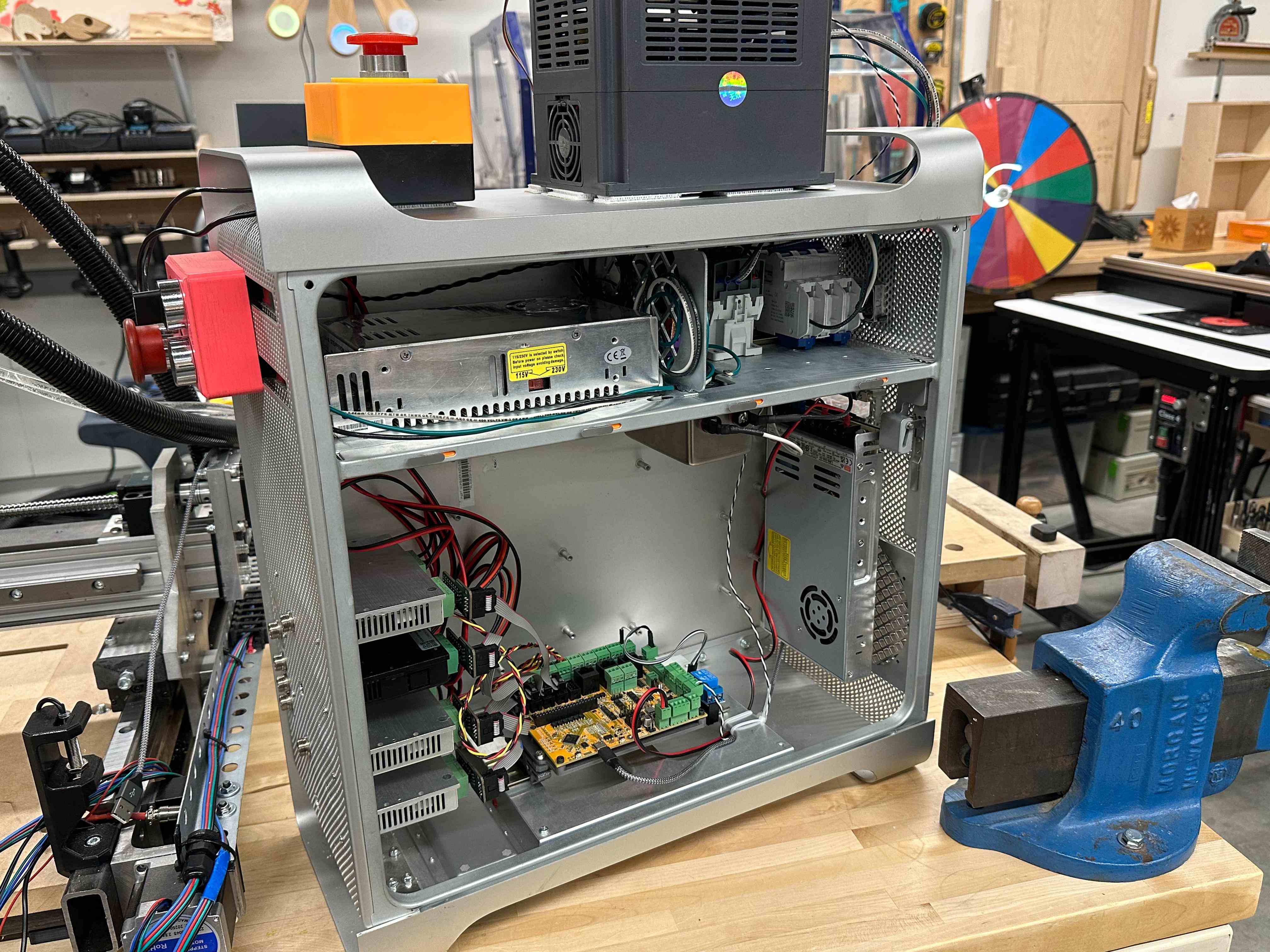
Electronics Enclosure & EMI
The electronics are housed in a repurposed 2009 Mac Pro aluminum enclosure. It was free, mechanically rigid, clean looking, and large enough to allow a disciplined layout without fabricating a custom box. The enclosure's internal aluminum divider probably originally intended to isolate the PSU—became a useful constraint for noise-domain separation. I used it to physically separate AC power components from DC/control electronics where possible, but I treated it as a guideline rather than a strict rule when serviceability or airflow would suffer.
Three AC-related components could not fit inside the divider volume and were placed intentionally with EMI and routing in mind: the VFD (mounted on top of the enclosure), the line filter (mounted directly to the divider for solid chassis coupling), and the 24V PSU (placed in the DC section but bonded to the chassis and kept far from control wiring). The VFD's plastic housing does not provide shielding, so noise mitigation relies on filtered input power, short AC routing out the rear, and complete physical separation of the spindle cable from all signal and DC wiring.
Stepper drivers are mounted directly to the aluminum chassis for both thermal and electrical reasons. Control electronics sit centrally in the DC section with short return paths and predictable current flow. Cable routing was treated as a primary design constraint: the front of the enclosure is reserved for stepper, limit switch, and DC/control lines, while the rear carries AC mains and filtered power to the VFD. The only unavoidable crossover is the VFD control interface, which uses RS-485 differential signaling over twisted pair for robustness in a noisy environment.
The result has been stable operation despite the compact enclosure and VFD: no controller resets, no communication dropouts, and no false limit switch triggers. The layout is a balance of cost, availability, and EMI behavior rather than an idealized enclosure-first design.
Safety Latching Circuit
A CNC mill is a powerful machine that is capable of causing serious harm if not handled properly. This makes it important to have a mechanism to quickly shut power to the machine in case of an emergency. The safety latching circuit serves this purpose. The key components that enable this functionality are the Emergency Stop (E-Stop) button, Start button, Contactor Coil. The E-Stop button is normally closed and latching, meaning that pressing it breaks the circuit and it stays broken until the E-Stop is manually reset. The Start button is normally open and momentary, meaning that pressing it closes the circuit only while it is being pressed. The Contactor Coil(NO) is an electromechanical switch. The contactor is switched by electrically energizing a coil which creates a magnetic field that pulls a set of poles into contact, thus closing the circuit between the poles and allowing power to flow through the contactor. When the coil stops being energized, the poles are pulled apart, opening the circuit and stopping power flow.
Safety Latching Circuit Block Diagram. A1 and A2 are the coil terminals of the contactor. The contactor's poles are (L1 > T1), (L2 > T2), and (Aux1 > Aux2).
AC Live flows through the breaker and control fuse to the E-Stop (Normally Closed). The circuit to the coil is completed when the Start button (Normally Open) is pressed. This closes the circuit and energizes the Contactor Coil. Once energized, the Contactor's own Auxiliary Contact closes, Since the auxiliary contacts connect E-stop output terminal to the coil terminal in parallel with the Start button, it maintains power to the coil even after the Start button is released which latches the circuit on. To cut power to the machine, the E-Stop button is pressed which breaks the circuit to the coil, de-energizing it and opening the contactor poles which cuts power to the machine.
Building the Machine
CNC machining ball screw nut block on a Prototrak Mill
I started by sourcing the parts that are purchased rather than fabricated, since their dimensions are harder to control and the rest of the design needs to be built around them. That list included linear rails, bearings, ball screws, stepper motors, and the spindle.
Early plate iterations began with 3D-printed parts to validate fit and catch stress concentration zones, but tolerances limited what I could learn from them. The next iteration used scrap aluminum plates that were thinner than the final target thickness and not large enough to cut full profiles, which exposed new alignment and assembly issues before committing to final stock.
Build Sequence (High-Level)
- Built the frame and installed Y-axis linear motion components.
- Machined and mounted plates coupling the Y-axis components to the gantry beam.
- Assembled the gantry beam and installed X-axis linear motion components.
- Crude electronics hookup to test X/Y motion (safety circuitry not yet in place; 24V PSU used for everything; no spindle or VFD yet).
- Mounted plates coupling X-axis motion to the Z-axis faceplate (iterated on plate thickness).
- Added top and bottom boxing plates to couple the two 2060 extrusions and improve torsional stiffness.
- Installed Z-axis faceplate, linear motion components, and tram plate.
- Second electronics hookup to test X/Y/Z motion (safety circuitry in place; spindle/VFD not yet installed) and added a 3D-printed Y-axis cable chain.
- Alignment and squaring improvements.
- Machined spindle clamp surfaces to add precise mounting holes.
- Added spindle (initially driven by PWM) and implemented a first, crude water-cooling setup.
- Programmed the VFD for spindle speed control and RS-485 communication with the FlexiHAL.
- Crude spoilboard mounting setup and first test cuts (wax, then surface milling a small section of the spoilboard).
- Replaced 3D-printed Y-axis stepper mounts with a machined steel angle.
- Added Y-axis limit switches, squared the X/Y axes, and continued test cuts (larger spoilboard surfacing and facing an aluminum plate).
Open Work / Next Iterations
- Machine Y-axis floating block mounts.
- Machine a new ball screw nut block to improve assembly and allow alignment adjustment.
- Replace the spindle cable with shielded cable.
- Upgrade spoilboard/workholding to a stiffer, more secure setup.
- Test Y-axis limit switch repeatability and improve alignment if needed.
- Design and install an X-axis limit switch (lower priority).
- Install a Z-axis limit switch.
- Improve wire management.
- Add a dedicated workholding plate.
- Consider a stainless workholding plate that also provides locating features for squaring the frame tubing.
Testing the Machine
The video shows the machine facing a 150mm by 150mm aluminum plate. Starting feedrate was 700mm/min and it was increased by 100mm/min until it reached 1400mm/min towards the end of the operation. Surface finish was spectacular (at least visually and by touch). There are also barely any noticeable changes in the surface finish as the feedrate increases which signals that this operation is pretty conservative which is very exciting.
The video shows testing the backlash of the Y axis by moving the Y axis back and forth and checking the difference between the starting position and the position it goes back to with a dial indicator. The result shows backlash that is less than 0.0005" over multiple iterations which is the smallest we can measure with the dial indicator. So, excellent result, somewhat unsurprising since ball screws were chosen largely to reduce backlash but I am very happy that no other source of backlash creeped in.
A lot more stress testing is still needed and to be done.